Before you compare ladder standoffs, put a tape across the wall around the window—not across the glass alone. A product’s published span does not tell you whether both arms will land on surfaces its manual permits.
Draw the opening or obstacle, the usable support band on each side and the clearance needed in front of it. Then identify the exact ladder and standoff attachment. The buying decision closes only when the front view, side view, ladder geometry and current manual all agree.
Do this after the job has passed the broader window-cleaning ladder type, load and site checks. A standoff can change top contact; it cannot authorize the ladder, repair an electrical conflict or replace a ground method that already completes the job.
The wall around the window is the product test
“Fits around a window” hides two different questions. First, is the accessory wide enough for its arms to clear the opening or projection? Second, is there a strong, permitted surface under each arm at the exact position created by that model?
A window frame is not automatically a support. Neither is glass, a rain gutter, roof covering, corner or strip of siding. The building owner, site plan and exact product instructions determine what can carry the contact. Your drawing should name that surface rather than label everything outside the glass “wall.”
| Site field | What to measure or identify | What it prevents |
|---|---|---|
| Opening or obstacle | Outside width of everything the arms must clear—not just visible glass | Comparing a product with an undersized glass measurement |
| Left support band | Continuous area where the left arm is permitted to bear | Landing partly on trim, glass or an unsupported edge |
| Right support band | Continuous area where the right arm is permitted to bear | Assuming a symmetrical wall when one side is obstructed |
| Clearance depth | Distance from the chosen support plane to the furthest part that must be cleared | Treating span as though it also measures distance from the wall |
If either support band is absent, the answer is not a wider accessory. Change the contact location or the access method. The ground-based options for high windows remain the first alternative when they can complete the entire cleaning sequence from a stable position.
Draw the contact zone before opening product tabs
Make two small drawings for one opening. The front view records where the arms could land. The side view records what they must clear. Do not force a product’s dimensions into the drawing yet.
| Drawing entry | Record | Ready when |
|---|---|---|
| Front: obstacle boundary | Total outside width and what each edge is made from | The full obstruction—not only the pane—is measured |
| Front: contact bands | Left/right band start, width, surface identity and excluded seams/trim | Both arms can fit wholly inside permitted bands |
| Side: support plane | Exact plane the arms would touch | Its strength and use are owned by the site plan |
| Side: furthest projection | Perpendicular depth from that plane to the obstacle edge | The measurement basis can be compared with the exact product’s standoff depth |
| Position restrictions | Wall, corner, roof, gutter, slope and orientation wording from the current manual | The proposed contact is explicitly inside the product’s allowed position |
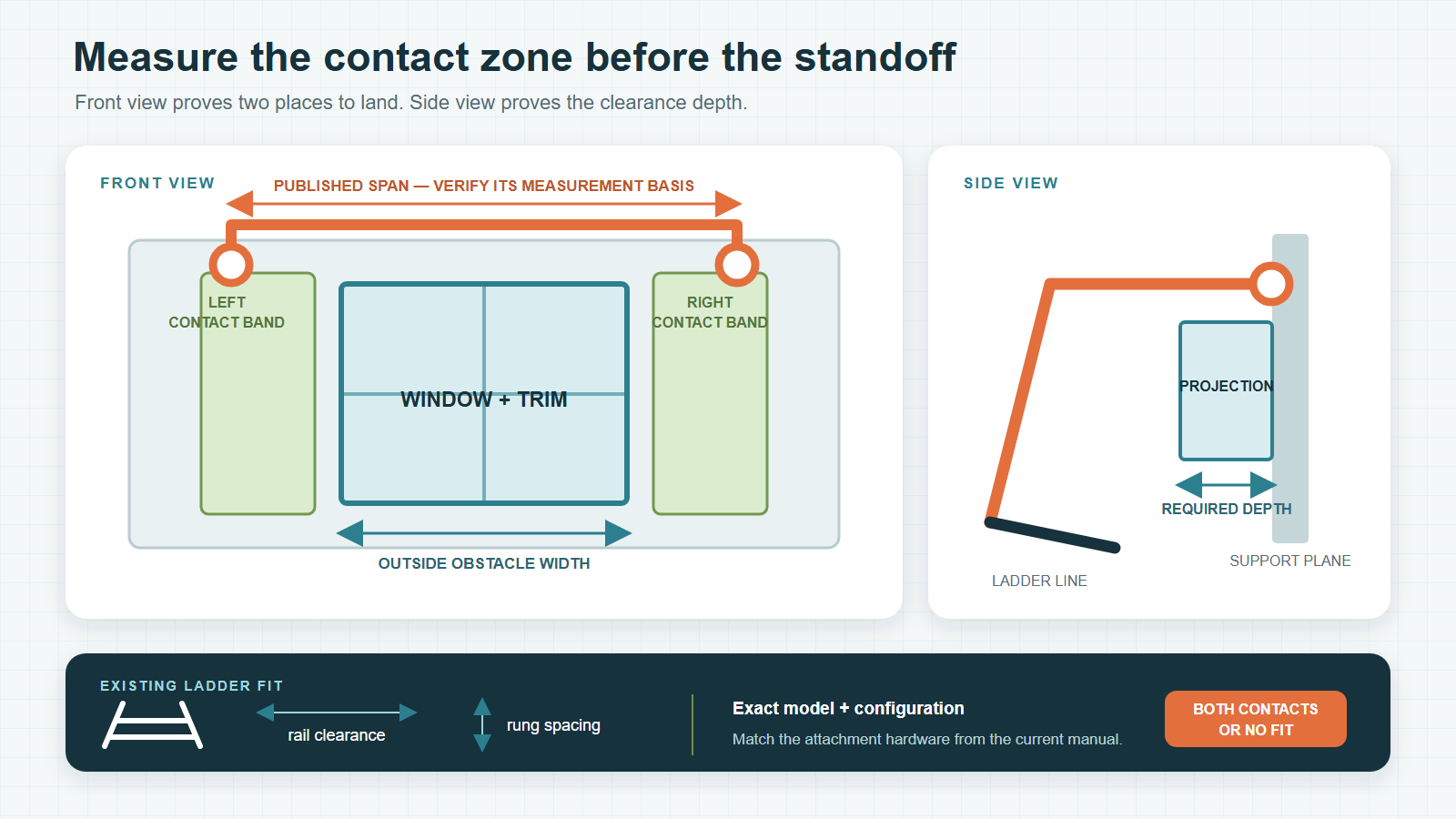
Published “width” may describe overall assembly span rather than pad-center distance or usable opening clearance. Keep the manufacturer’s own term and measurement basis. If the technical drawing does not show where the number begins and ends, ask for that drawing; do not subtract a guessed arm or pad width.
Make the existing ladder pass before the wall
The accessory must attach to the ladder you own in the configuration you will use. A category label such as “extension ladder stabilizer,” a similar rung shape or the word “universal” does not close that fit.
Start with the ladder manufacturer, family, exact model and current label. Then use the standoff manufacturer’s model list or measured geometry. Depending on the product, the deciding fields may include inner width between rails, rung spacing, rung depth, overlapping rungs, extension position and the exact bracket, clamp, pin or bolt hardware.
| Fit field | Evidence to retain | Hold condition |
|---|---|---|
| Ladder identity | Manufacturer, model, material, configuration and label photo | Only size or ladder type is known |
| Geometry | Measurements named by the exact standoff source | A required rail/rung value is missing or outside the range |
| Attachment identity | Standoff model, selected arms and included/required hardware | Parts are mixed, unnamed or borrowed from another model |
| Current instructions | Manual tied to the exact model and its approved ladder position | A retailer description is the only fit authority |
| Pre-use owner | Who trains, inspects and withdraws the ladder/accessory if defective | The purchase is being treated as operating readiness |
For covered work, OSHA 1910.23 requires stable/level use unless secured or stabilized. It also calls for support at both upper side rails of a non-self-supporting ladder, except where a single-support attachment is fitted. That rule does not certify your wall or accessory. It shows why a product fit and a support fit are separate records.
Three current products use three different fit languages
Current manufacturer pages demonstrate why “standoff size” is not one universal field. These are evidence examples, not a ranking.
| Exact product/source | Published span and depth | Ladder-fit language | What remains to prove |
|---|---|---|---|
| Little Giant WingSpan 10111 | Fixed 50-in width; 12-in standoff | “Most” Little Giant aluminum and fiberglass articulating ladders | Exact ladder model, two permitted wall contacts and manual position |
| Werner AC78 QuickClick | 44-in span; 10-in standoff | Werner aluminum extension ladders | Exact current ladder model, contact bands and AC78—not AC96—requirements |
| Ladder-Max Multi-Pro MP2010 | Separate 13/19/24-in attachments; 51-in wide-span option for a stated 48-in window | Measured rails/rungs plus named configurations | Selected attachment, exact ladder measurements, contact bands and permitted position |
Little Giant’s product page also lists 5.35 pounds for model 10111 and describes it as aluminum. That weight belongs in the route’s ladder/accessory handling and inspection plan; it is not evidence that another standoff is easier or harder to manage.
The current Ladder-Max fit FAQ makes its broad ladder language measurable: more than 11.75 inches between side rails, rungs 12 inches on center and rung depth no more than 2 inches. Some multi-position ladders fit only in extension position when the rungs do not overlap. If one value fails, “fits all major ladders” does not rescue the cart.
Roof, gutter and slope permissions do not transfer
The current Little Giant WingSpan manual says not to rest the arms on a roof or rain gutters, not to use them on uneven or sloped surfaces, and to keep them perpendicular to the wall or surface. It also calls for the accessory to be secure before each use.
Ladder-Max, by contrast, declares direct roof placement for its named MP2010 system and offers separate corner and depth attachments. That is not a contradiction to “solve” with a generic ladder rule. It is proof that contact permission belongs to the exact product and selected attachment. The WingSpan restriction remains the WingSpan restriction; the MP2010 declaration remains an MP2010 fact.
| Proposed contact | Evidence needed | If the exact manual is silent or says no |
|---|---|---|
| Flat wall around the window | Two strong permitted bands plus the manual’s required arm orientation | Change the bearing location or accessory |
| Corner | Named corner attachment and exact current instructions | Do not improvise a V-position |
| Roof surface | Exact product permission plus the site’s roof/support/access plan | Do not transfer MP2010 wording to another model |
| Rain gutter | Exact manufacturer permission and site structural authority | Treat the gutter as an obstacle to clear, not a default support |
| Uneven or sloped area | Exact product position and site plan that permit it | Use a different contact/access plan |
Training and inspection remain outside the product comparison. OSHA 1910.30 assigns covered equipment care, inspection, storage and use training before use, with retraining when equipment, workplace or demonstrated knowledge changes. Read the exact illustrated manual with that owner; this page deliberately stops before installation and setup.
Let the failed field choose the next move
| What the record shows | Decision | Next move |
|---|---|---|
| The full job closes from stable ground | Use the ground method | Specify that system; remove the standoff from this job |
| Exact ladder fit, span/depth, two support bands and manual position all agree | Exact fit to verify | Retain the drawing, model/attachment and current manual with the site plan |
| The accessory fits the ladder but an arm misses a permitted band or the surface/position is unresolved | Change the contact or access plan | Move the bearing plan or choose a different authorized method—not merely a wider model |
| The ladder/model geometry, attachment hardware or product position conflicts | Reject this accessory | Do not modify the ladder, mix arms or borrow another model’s permission |
Only the accessory that survives those fields belongs in the professional window-cleaning equipment plan. Keep its exact ladder, attachment, contact drawing and manual together. “Fifty-inch standoff” is a shopping label; a reproducible fit is a named model on a named ladder with two permitted places to land.